JL Audio
10W1v3-2
300W RMS 10" Subwoofer


Overview
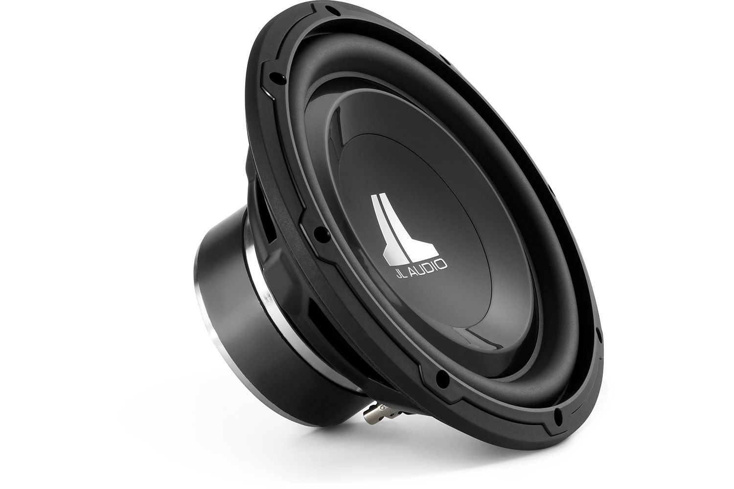
The 10W1v3 is an outstanding choice when space is very tight and amplifier power is moderate. It features shallow mounting depth (4.6” / 117 mm) and a compact motor structure, allowing it to comfortably fit in a lot of spaces where a typical 10” driver will not. Lacking a pole vent, the rear of the motor structure can be placed directly against an enclosure boundary. Excellent excursion capability and linearity allow it to reproduce sub-bass with shocking extension and quality. Several of JL Audio's proprietary technologies enhance its performance and reliability.
The 10W1v3-2 is best used with amplifier power in the 75W - 300W range and is optimized to operate in a compact 0.55 cu. ft. (15.57 L) sealed enclosure. Detailed enclosure recommendations can be found in the "Specifications" tab.
Dynamic Motor Analysis - DMA Optimized Motor
JL Audio's proprietary Dynamic Motor Analysis system is a powerful suite of FEA-based modeling systems, first developed by JL Audio in 1997 and refined over the years to scientifically address the issue of speaker motor linearity. This leads to vastly reduced distortion and faithfully reproduced transients... or put simply: tight, clean, articulate bass.
Elevated Frame Cooling
JL Audio's Elevated Frame Cooling design delivers cool air through slots directly above the top-plate to the voice coil of the speaker. This not only enhances power handling, but also sound quality by minimizing dynamic parameter shifts and power compression.
Many speakers employ venting techniques to enhance voice coil cooling. This is typically accomplished by having big holes in the sides of the frame just below the spider attachment shelf. While it provides a modest cooling benefit, this low-velocity air-flow does not blow directly or strongly on the voice coil.
Our design improves upon this cooling technique in a number of ways. By elevating the frame above the top-plate of the motor (via stand-offs integrated into the bottom of the frame) a narrow, high-velocity air-path is created between the bottom surface of the frame and the top surface of the top-plate. This air path leads directly to the voice coil and then turns upward into the spider air cavity. By utilizing the pumping action of the spider through this focused air path, a large volume of cool air hits the coil windings directly.
Another important benefit is that the upper surface of the top-plate (one of the speaker's hottest parts) is directly exposed to cooling air flow, whereas on a conventional design it is isolated from the air flow by the lower flange of the frame. The elevated frame technology greatly increases thermal power handling, reduces compression effects and does so without any additional parts.
Engineered Lead-Wire System
Carefully engineered lead-wire design and attachments ensure controlled, quiet lead-wire behavior under the most extreme excursion demands.
Managing the lead-wires on a long-excursion woofer is one of the trickier aspects of its mechanical design. To address this, many long-excursion woofers today rely on a simple solution that weaves the lead-wires into the spider (rear suspension) of the driver.
The biggest problem with this approach is that spider limiting behavior plays a hugely important role a woofer's performance. Lead-wires that are attached or woven into the spider material can alter the spider's "stretching" behavior. The tinsel wire naturally has less 'give' than the fabric material of the spider leading to asymmetrical spider behavior and non-uniform stress distribution around the spider circumference. The wire attachment points can also cause localized pulling and tearing forces at the spider's excursion limits. As such, longevity becomes a major concern and makes the woven-in design less than ideal for very long-excursion designs.
While a traditional 'flying lead' design does not compromise spider linearity or radial stability, it creates its own challenges on a long-excursion woofer. Managing the 'whipping' behavior of the wire and making sure it does not contact the cone or spider is one challenge. Another is ensuring that the leads do not short one another or the frame of the woofer.
To overcome these issues, JL Audio's engineered flying lead-wires work in conjunction with carefully engineered entry and exit support structures molded into the terminals and the voice coil collar. Some models also feature jacketed lead-wires to further reduce the likelihood of shorting and fatigue.
The result is flawless high-excursion lead-wire behavior, with outstanding reliability and none of the compromises inherent to a woven-in lead wire system. Building woofers this way requires much more labor and parts complexity than the simpler woven-in approach, but the payoff is in reduced distortion, reduced mechanical noise and improved reliability.
VRC® Vented Reinforcement Collar
JL Audio's Vented Reinforcement Collar (VRC®) improves the rigidity and stability of the cone/spider/voice coil junction and directs airflow over the voice coil windings for improved thermal performance.
The Vented Reinforcement Collar (VRC®) is a composite structure that addresses two issues related to reliability. By reinforcing the critical junction between the cone, voice coil and spider, the VRC greatly reduces failures due to glue breakdown or material weakness. It does this by greatly increasing adhesive contact area and providing stress relief to the spider material at excursion extremes.

The VRC® also features slots that facilitate air flow directly onto the voice coil windings. This reduces thermal compression effects and enhances reliability. Current versions of the VRC® also incorporate lead-wire strain relief structures to improve mechanical reliability.
FCAM™ Floating Cone Attach Method
This assembly technique, conceived by JL Audio, ensures proper surround geometry in the assembled speaker for better excursion control and dynamic voice coil alignment.
JL Audio's patented FCAM™ technology is an innovative method of bonding the surround/cone assembly to the voice coil former/spider assembly. This feature helps ensure concentricity of the surround, spider and voice coil without torquing the suspension to achieve it. This allows for the inevitable, slight variations in production part dimensions without having them negatively impact the integrity of the suspension and coil-centering at high excursions.
Insert Molded Sub-Assembly
Spiders, voice coils, terminals and lead wires are preassembled, using a patented process, onto a composite carrier for improved precision and reliability.
A conventional speaker is assembled in layers. In other words, multiple parts are assembled and glued sequentially into the basket, leading to stacking of tolerances and making it difficult to achieve optimal assembly precision.
JL Audio's patent-pending insert-molded spider carrier permanently bonds the spider to a mechanically robust carrier that also incorporates the terminal assembly and lead wire strain relief features for enhanced reliability and optimal alignment of parts. This subassembly is assembled outside the speaker basket, for optimum alignment and glue-joint integrity. The benefit is a more precisely built, more mechanically sound loudspeaker.
Built-In USA with Global Components
At a time when most audio products are built overseas, JL Audio’s commitment to in-house loudspeaker production continues to grow. To pull this off in a competitive world market, our production engineering team has created one of the world’s most advanced loudspeaker assembly facilities and established a global network of quality component suppliers who build to our specifications. This, combined with our commitment to state-of-the-art assembly technology, allows our skilled workforce to efficiently build JL Audio products to extremely high quality standards, right here in the U.S.A.
Specifications
Power

Dimensions

Parameters
Sealed Enclosure Specifications

Enclosure Notes
The enclosure recommendations listed above are external dimensions which assume the use of 0.75” (19 mm) thick material. If you are using 0.625” (16 mm) thick material, subtract 0.25” (6.5 mm) from each dimension. Do not use any material with a thickness of less than 0.625” (16 mm) as this may compromise the rigidity of the enclosure.
All enclosure volumes listed above are net internal volumes! Driver displacement, port displacement and brace displacement must be added to obtain the final gross internal volume. All enclosure dimensions above have already taken this into account.
When using multiple subwoofers in a common enclosure you will need to recalculate the enclosure and port dimensions. For assistance please contact your authorized JL Audio dealer or JL Audio Technical Support.
We recommend the use of this speaker in a bi-amplified system using high-quality satellite speakers and a high-quality amplifier. We do not recommend the use of this subwoofer with a passive crossover (coil), as this type of device will adversely affect performance.
All specifications are subject to change without notice.
Safety Notice
Prolonged exposure to sound pressure levels in excess of 100dB can cause permanent hearing loss. This high-performance speaker can exceed this level. Please exercise restraint in its operation in order to preserve your ability to enjoy its fidelity.
When installing a subwoofer in your vehicle, it is extremely important to secure the enclosure firmly. We recommend bolting the enclosure through the metal of the floorpan or the frame of the vehicle with large diameter washers for reinforcement. If an enclosure is not firmly attached, it can become a projectile in a collision. This is particularly important in a hatchback, station wagon, sports utility vehicle, or van.
Ported Enclosure Specifications

Safety Notice
Prolonged exposure to sound pressure levels in excess of 100dB can cause permanent hearing loss. This high-performance speaker can exceed this level. Please exercise restraint in its operation in order to preserve your ability to enjoy its fidelity.
When installing a subwoofer in your vehicle, it is extremely important to secure the enclosure firmly. We recommend bolting the enclosure through the metal of the floorpan or the frame of the vehicle with large diameter washers for reinforcement. If an enclosure is not firmly attached, it can become a projectile in a collision. This is particularly important in a hatchback, station wagon, sports utility vehicle, or van.

| Brand | JL Audio |
|---|---|
| RMS Power | 300W RMS |
| Shallow Mount | No |
| Subwoofer Size | 10" |


